Picture a crank disc spinning like a steering wheel, with a pin stuck off-center near its rim. That pin traces a small circle as the disc turns. A rod connects the pin to a piston sitting inside a cylinder, and the whole cylinder is free to rock on a pivot behind it. As the pin swings around its circle, the cylinder has to tilt back and forth to keep the rod aimed at the pin, which is what pushes the piston in and out. No sliding crosshead, no rod guide, just geometry chasing a moving point.
Sand cast, machined, and tumbled
The base plate was sand-cast in 6061 aluminum, then every mating surface was machined to tolerance on a manual mill and lathe. This is the actual engine, not a render.
Finished engine at full speed
One pivot, one pin, two ports
This is the whole engine in section: the cylinder rocks on its trunnion stud while the crank pin drags the brass rod through its circle. Every dimension labeled here is taken straight from the part drawings; the layout itself is schematic.
Section schematic from the drawing set. The air port near the closed end sweeps across the two plate ports as the cylinder tilts, which is the entire valve system: no valves, no cam, just the rocking motion itself.
Two lines of trigonometry drive the whole mechanism
This is the general relationship every wobbler-style oscillating cylinder follows, the same math used to size the crank throw and predict cylinder tilt during design.
Let (Δx, Δy) be the vector from the trunnion pivot to the crank pin. The cylinder's tilt is just the angle of that vector:
cylAngle = atan2(Δy, Δx)
The piston has to extend far enough to reach the pin from the trunnion, so its length is the vector's magnitude:
pistonExt = √(Δx² + Δy²)
The crank pin itself just traces a circle of radius r (the crank throw, 0.30 in) around the shaft centerline, at whatever angle θ the disc has rotated to:
pin.y = shaft.y + r·sin(θ)
pin.z = shaft.z + r·cos(θ)
That's the entire mechanism: one circle, one angle, one distance. Every other quantity, connecting-rod length and orientation, piston travel, cylinder tilt angle at any given crank position, falls straight out of these three lines.
2,340 RPM puts real load on the crank pin
The crank pin isn't just tracing a circle for show, it's constantly accelerating toward the shaft centerline to stay on that circle. That acceleration is what the pin, the connecting rod, and their fits actually have to survive at speed.
Centripetal acceleration only needs the crank throw r and the angular speed ω, both already fixed by the geometry and the RPM this engine hit on the bench:
ω = 2π·RPM ÷ 60 = 2π·(2340) ÷ 60 ≈ 245 rad/s
a = ω²·r = (245)²·(0.30 in) ≈ 18,000 in/s² ≈ 46.6 g
Almost 47 g on the crank pin at top speed, that's the number that actually drives material choice, fit tolerance on the pin-to-rod joint, and why the frame needed to be sand cast rather than 3D printed. It's also why the design has a real speed ceiling: push RPM higher and this number climbs with the square of it, not linearly.
Turning 46.6 g into a load case
The centripetal number from section 04 is only useful if it goes somewhere. Here it becomes a static study on the crank disk: the full mass of the brass rod, lumped at the pin as a worst case, pulling radially outward at top speed.
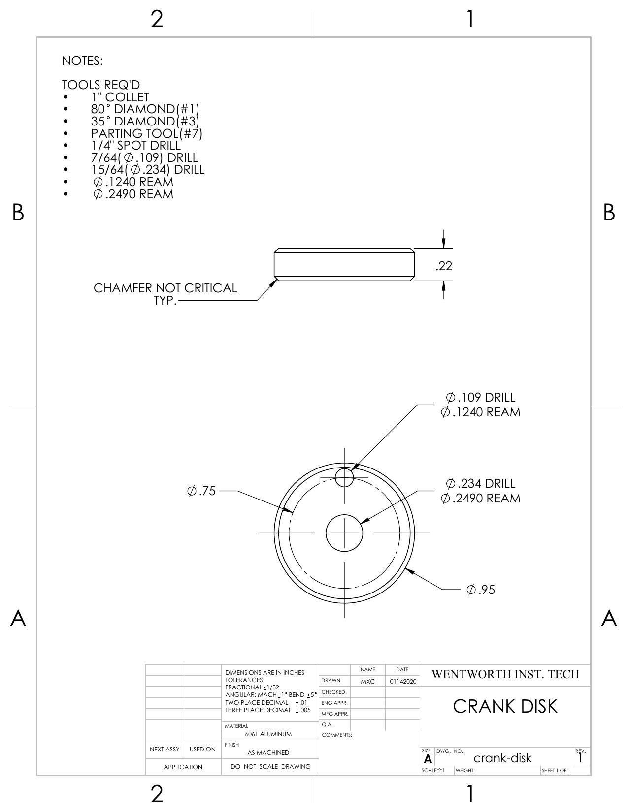
Crank disk drawing · Ø0.95 × 0.22 in, 6061 Al · shaft bore Ø0.2490 ream, pin hole Ø0.1240 ream
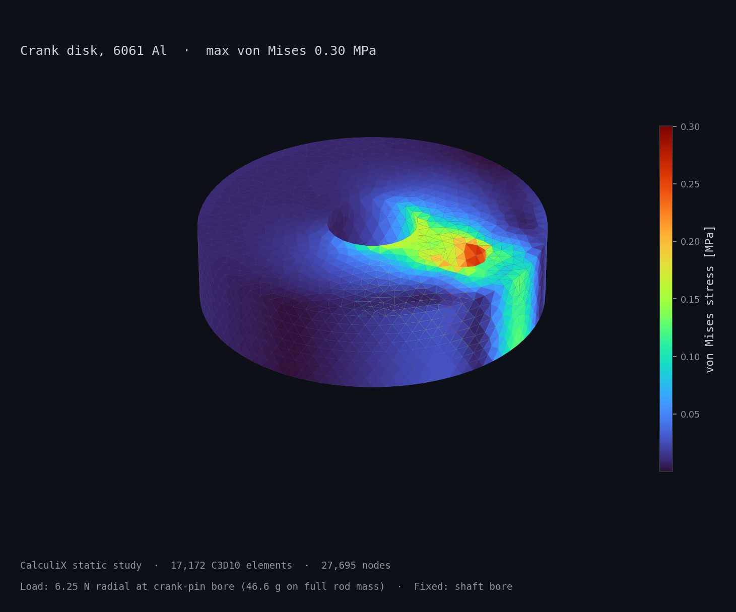
CalculiX static study, second-order tets · stress peaks at the loaded pin bore and dies off toward the fixed shaft bore
The load is the rod's mass under the 46.6 g centripetal field, and a quick bearing-stress hand check sets the expectation before the solver runs:
mrod = ρbrass · V = 0.030 lb          F = m·a = 0.030 · 46.6 ≈ 1.4 lbf (6.25 N)
σbearing ≈ F ÷ (d·t) = 1.4 ÷ (0.124 · 0.22) ≈ 52 psi ≈ 0.36 MPa
The solver lands in the same place: max von Mises 0.30 MPa on 17,172 C3D10 elements, against a 6061-T6 yield around 276 MPa. That is a factor of safety near 900.
Assumptions: full rod mass lumped at the pin, shaft bore fully fixed, rotating load applied as a static radial force, T6 properties. The result matches what the bench work showed: the disk is nowhere near its material limit, so the real speed ceiling lives in the pin-to-rod fit and its wear, not in disk stress.
Every part has a dimensioned drawing behind it
Each part was machined to a toleranced drawing (ASME Y14.5-2009): two-place decimals at ±.01, three-place at ±.005. The two below governed the cylinder, the part that took three attempts, and the plate everything mounts to.
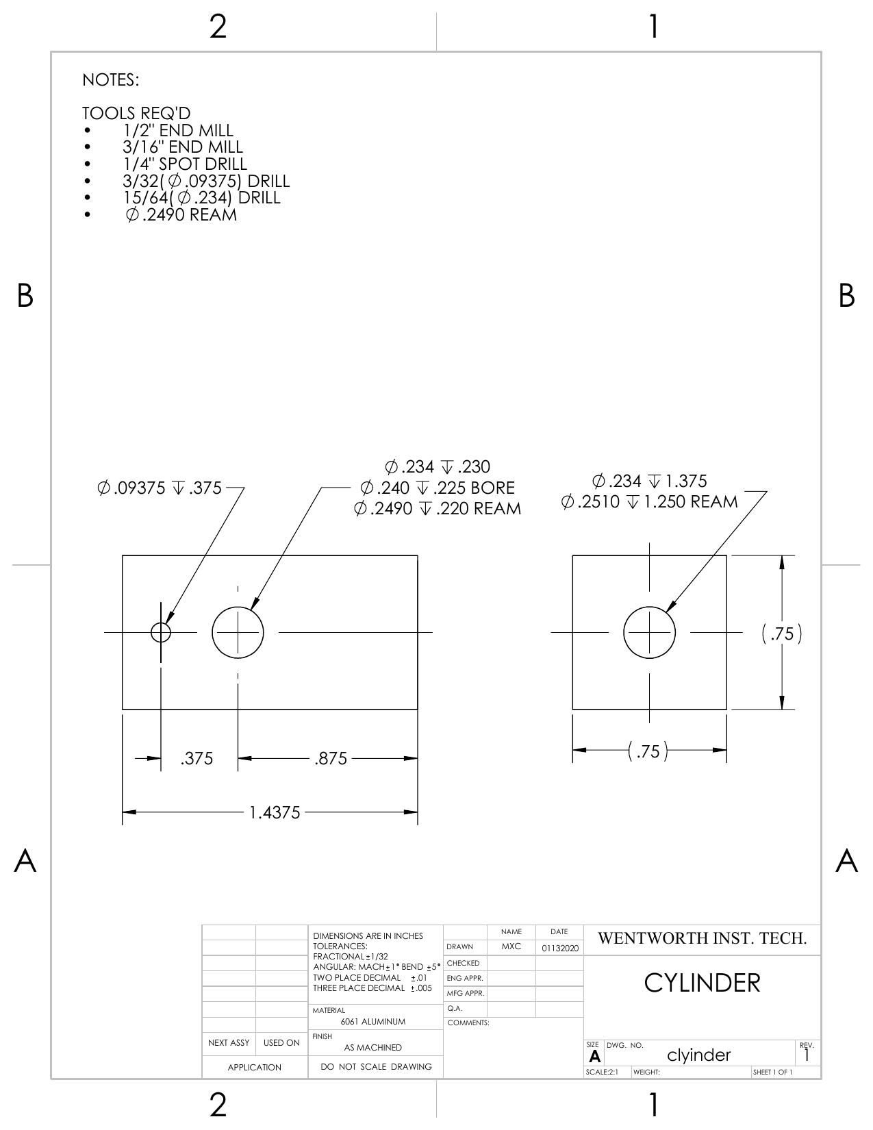
Cylinder · bore Ø.2490 ream × 1.25 deep, port Ø3/32 · the part that took three attempts on the lathe
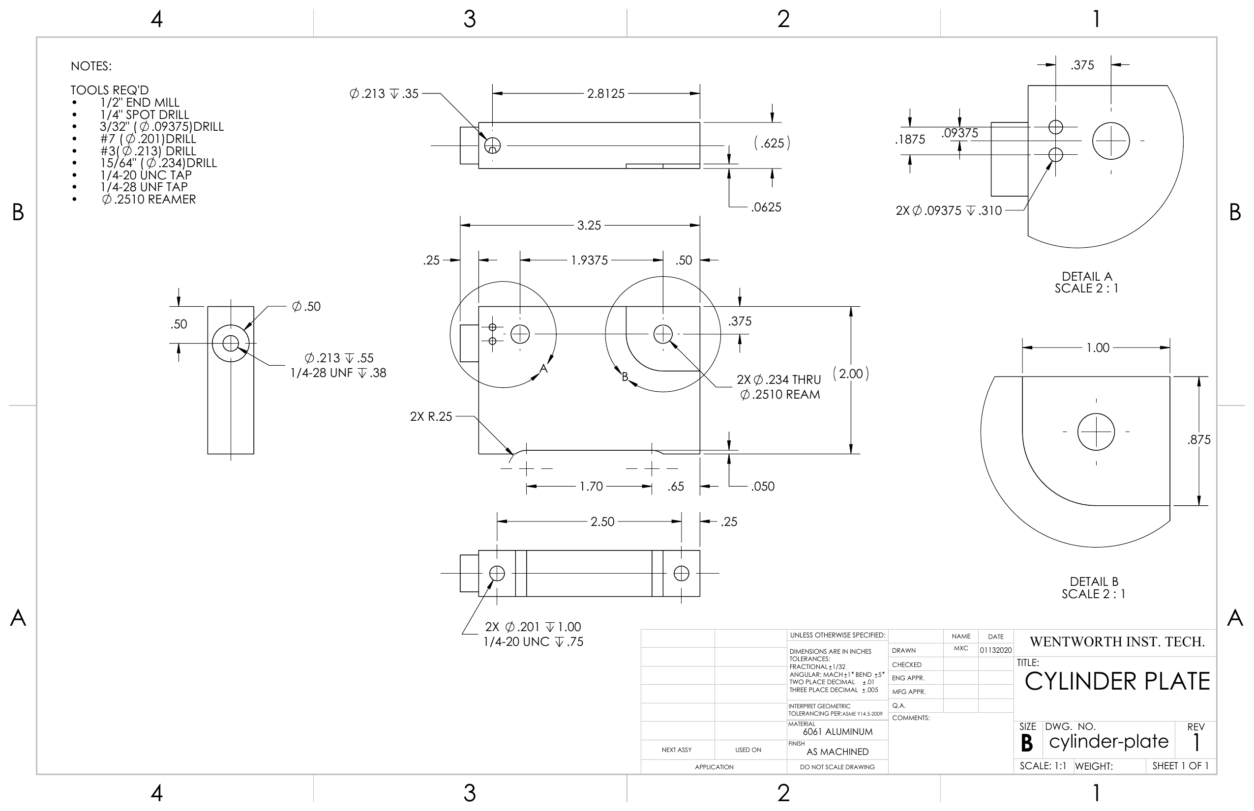
Cylinder plate, B-size · ASME Y14.5-2009 · detail views call out the two Ø3/32 air ports and tapped pivot boss
What got rejected, and why
The finished engine shows the outcome. These are the calls from the per-part build reports that got it there.
3D-printed frame → sand-cast 6061, then machined
The 46.6 g crank-pin load at 2,340 RPM ruled printing out, and casting gave near-net shape cheaply. The plan assumed casting defects: porosity and short fills showed up as expected, and face milling with machining allowances cut them back out of the mating surfaces.
salvage the botched port → fresh part, every dimension re-checked
An oversized spot drill left an air gap at the 3/32 in port, and the salvage attempt of drilling from the opposite face met the original hole and made it a through hole. The lesson stuck: the final cylinder was machined with each dimension verified before every operation.
nominal bore depth → extra closed-end wall
The bore leaves only 0.0625 in of clearance at the closed end, and the second attempt drilled straight through. The final part deliberately carries extra length so a through-drill is impossible: a little dead volume traded for a part that survives its own machining.
From drawing to bench test
Full engineering drawings (ASME Y14.5-2009), the assembly report, and per-part manufacturing writeups are in the GitHub repo linked above, along with an accurate 3D scan of the finished assembly.
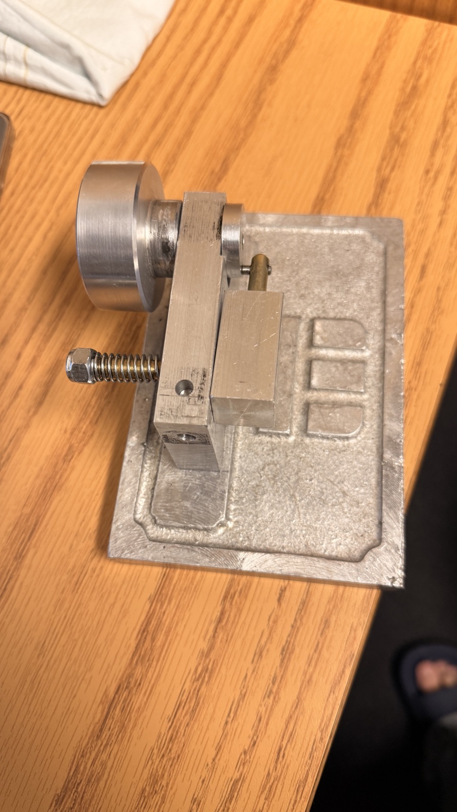
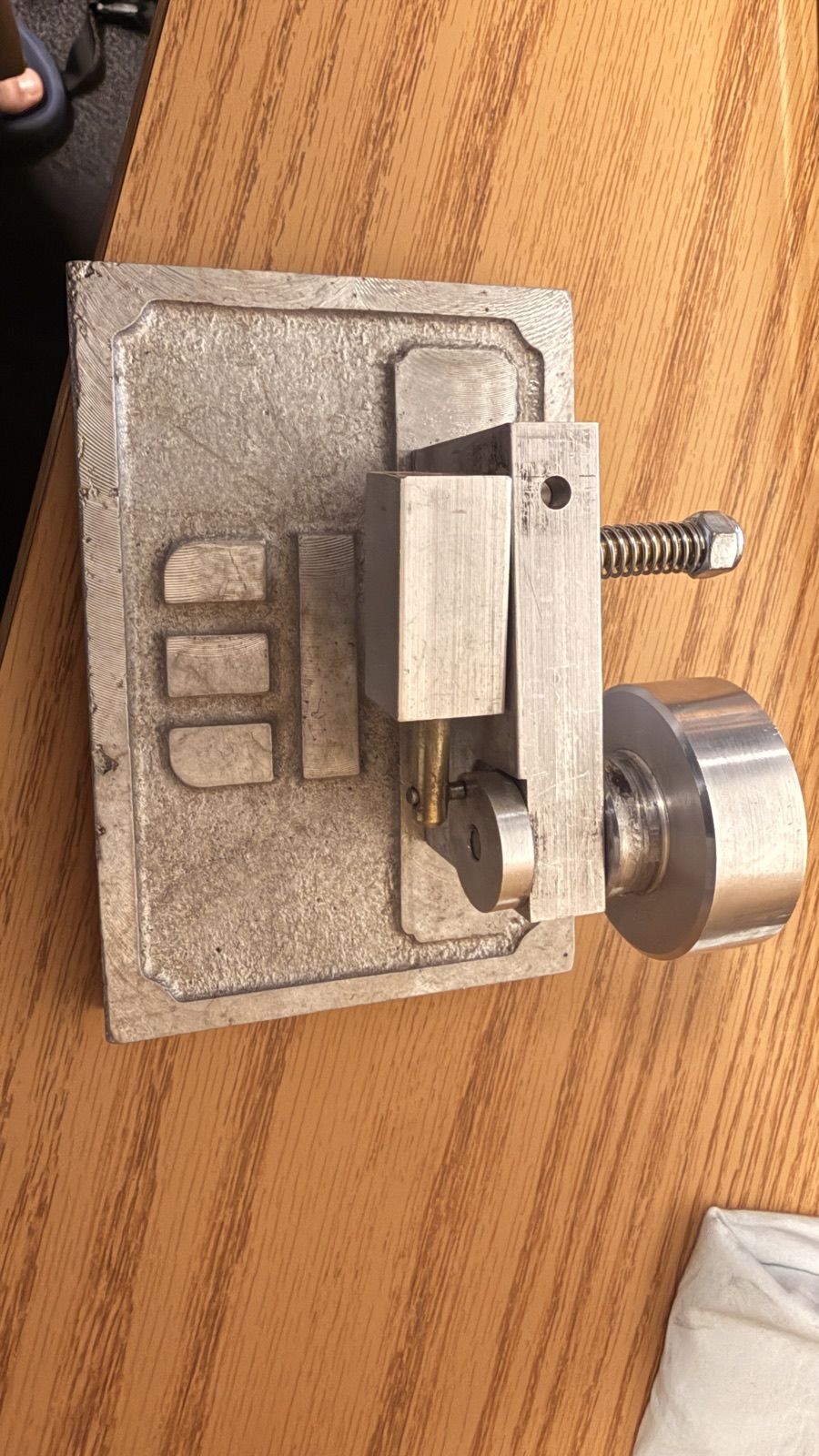
Photogrammetry scan of the finished assembly, turntable render · the same file is in the repo as a GLB