Think about how a scissor lift usually shows up on a jobsite: on a trailer, rolled off outside, too wide for a hallway. X-FLEX asks what happens if you shrink that machine down to elevator width without losing real lift capacity. The team's early concept used tank tracks, a hydraulic pump, and a PLC controller, the same building blocks a full-size lift would use. As the design matured, every one of those got reworked into something that fits a machine this small: wheels instead of tracks, a single electric linear actuator instead of a hydraulic pump, and an Arduino instead of an industrial PLC. This page walks through that rework, and the electronics and control logic I owned.
The original concept, and why it changed
The first full-assembly concept model used tracked treads for traction and a hydraulic cylinder for lift, closer to how an actual full-size scissor lift is built. Packaging that into a doorway-width chassis turned out to fight the whole point of the project.
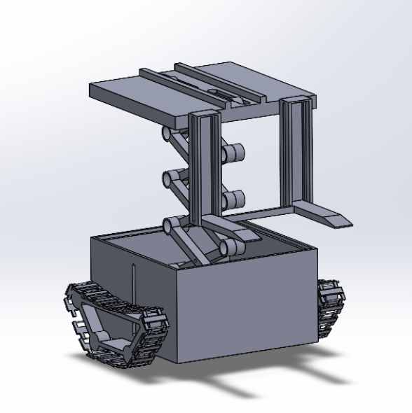
Early concept assembly · SolidWorks · tank tracks + hydraulic lift
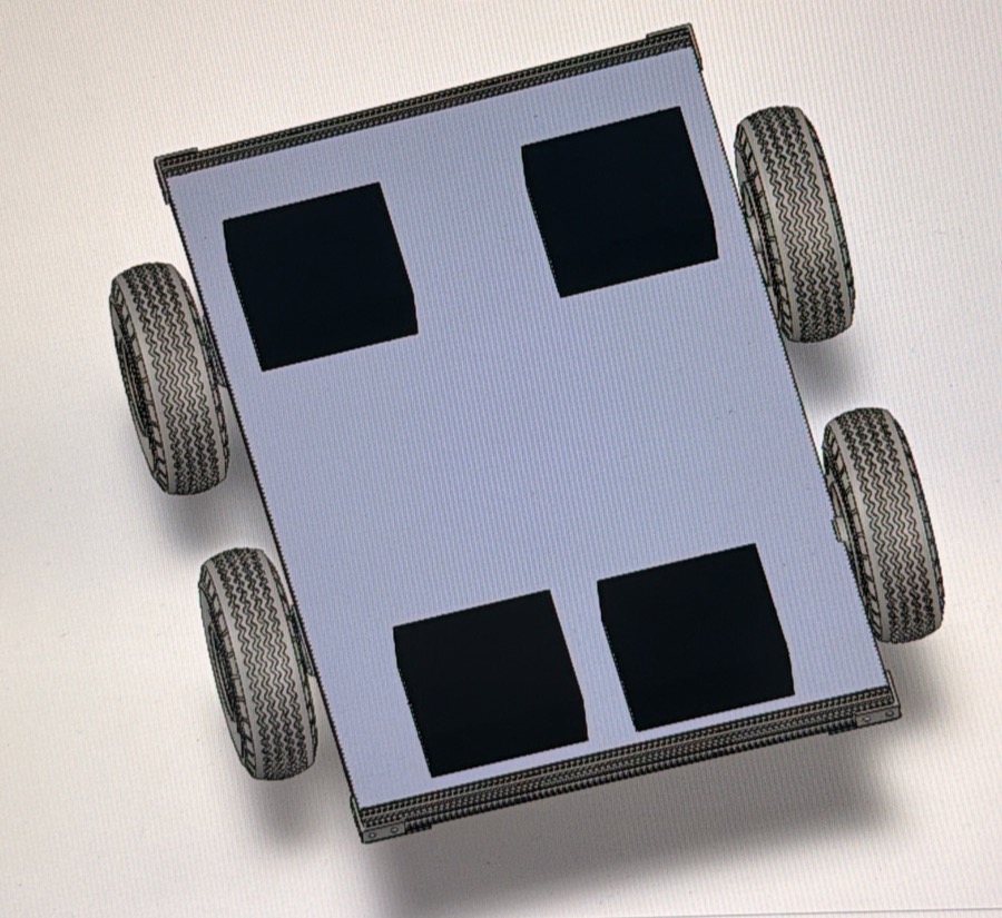
Reworked base frame in SolidWorks, captured during a design review · four-wheel differential drive
Tracks add width and mechanical complexity for traction the wheeled base didn't need at this scale; a hydraulic pump adds a reservoir, hoses, and a second failure mode alongside the electrical system. The team moved to a four-wheel chassis with chain-and-sprocket differential drive, and a single 24V linear actuator handling lift in place of the hydraulic pump.
Arduino Mega, FlySky RC, and two motor drivers
This is the part of the system I owned. An Arduino Mega 2560 reads the FlySky RC receiver's PWM channels, mixes throttle and steering into independent left/right motor commands, and drives two Cytron MDD10A motor drivers for the chain-and-sprocket differential drive.
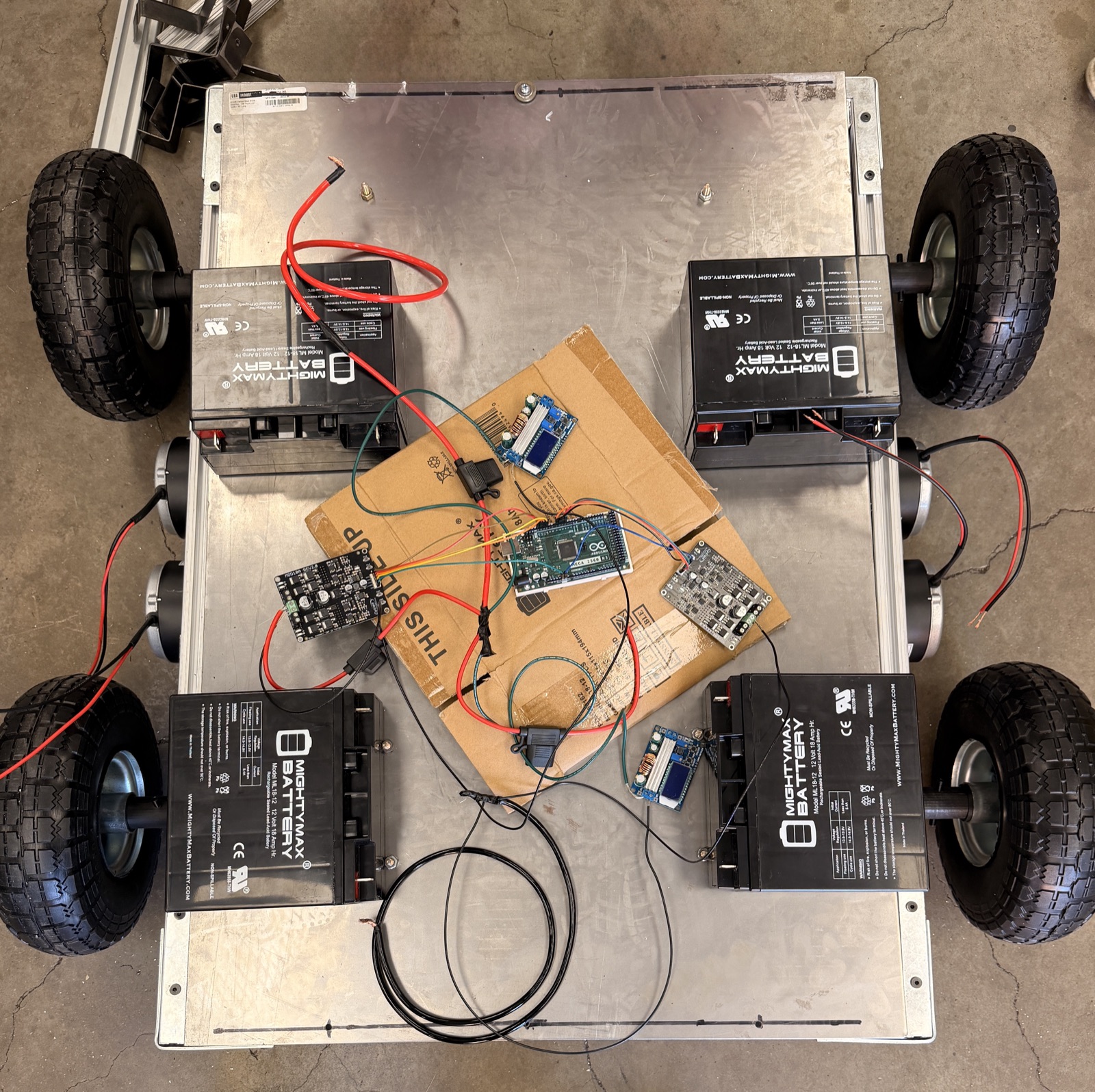
Bench test · Arduino Mega 2560, dual Cytron MDD10A drivers, 12V batteries wired direct to the base frame
Differential drive doesn't turn the wheels directly with steering input, it turns the difference between the left and right side. Throttle and steering both range from −1 to 1, and get mixed into a per-side command before it goes to the motor drivers:
left  = clamp(throttle + steering, -1, 1)
right = clamp(throttle - steering, -1, 1)
Full throttle with zero steering drives both sides equally, straight ahead. Zero throttle with full steering spins the base in place, left and right sides commanded in opposite directions, the same logic a tank or a wheelchair uses to turn on the spot.
Deadman and limit switches are wired in line with the actuator and drive circuits at the hardware level, not just checked in software: if the deadman switch is released or a limit switch trips, the motion stops regardless of what the Arduino is currently commanding. That's the fail-safe a remote-controlled lift needs when the person driving it can't always see every part of the machine.
Scissor arms, one actuator
The platform rides on three stacked scissor stages: paired fork arms that cross like an X, with each stage pinned to the one below it. A single 24V linear actuator stands near-vertical in the middle of the base and drives the whole stack through the stage-2 bars, which replaced the original hydraulic cylinder with one moving part and no fluid to leak or bleed.
Interactive: the slider extends the actuator and all three stages open together, one geometry shared by the whole stack. Height readout uses the as-built geometry: 8 ft at the 70° maximum arm angle, 25° stowed.
The report's sizing model for a symmetric multi-stage scissor puts the actuator demand at its worst the moment the lift leaves the stowed position. With the total Stage-1 load W (200 lb rated plus about 100 lb of deck and upper stages):
Fact = W·n / (2·tan θ) at θ₀ = 25°: 965 lb at θmax = 70°: 164 lb
Six times the force at the bottom of the travel than at the top. The actuator is sized by liftoff from stowed, not by holding load at 8 ft, and the pin and rod joints at the arm crossings are the highest-stressed features in the machine.
From the team's final report (center-pivot mount model, friction and arm weight ignored). Geometry: 34 in arms, three stages, 25° to 70° travel.
Two stages was the obvious layout. It loses on paper.
Same as-built arm section (1.5 × 1.5 × 0.120 wall A513 tube), same 300 lb Stage-1 load, solved in CalculiX for both stage counts. The only difference is the arm length each layout needs to reach 8 ft.
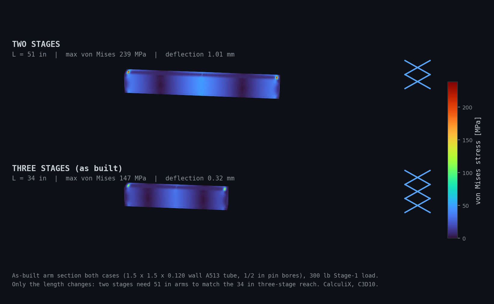
CalculiX static study, shared color scale · the two-stage arm peaks at 239 MPa and 1.01 mm against 147 MPa and 0.32 mm for the as-built 34 in arm. First-order load case (center-pivot force, ends fixed); the ratios are the design signal.
The trade is not free: more stages means more pins, more joints to fabricate, and more places to lose stiffness in slop; the report notes accumulated clearance across the pivot pairs shows up as platform wobble at height. But 51 in arms could not fold into a doorway-width chassis at all, so the packaging constraint and the stress numbers both pointed the same way. Three stages is what got built, and the finished lift held 200 lb at 8 ft.
What got rejected, and why
A model screenshot shows the outcome. These are the calls behind it, straight from the team's final report and engineering notebook, each one a trade made on purpose.
rubber tank tracks → four driven dolly wheels
The track set needed about $600 of belt material plus sprockets, idlers, and machining, and it was the single largest manufacturing risk in the project. Wheels cost about $30 and roll better on finished floors. The trade gave up loose-surface capability, which is why outdoor performance is listed as not yet validated.
hydraulic pump + cylinder → one 24V linear actuator
Hydraulic suppliers were still marked TBD with no schedule margin, and a fluid circuit brings leak and containment failure modes plus pressure-test bench time. One actuator ties straight into the 24V bus and its integral limit switches fold into the safety chain. The cost was lift speed and reach.
CLICK PLC + ladder logic → Arduino Mega 2560
When the forklift arm left the project, the case for industrial motion control left with it. Four motors need multi-channel PWM and 2.4 GHz RC decoding, which is outside what the CLICK does well. Safety did not move into the new controller's software; it moved into hardware.
two scissor stages → three
Two stages meant 51 in arms in place of 34, and with the same tube section that is 1.6× the peak stress and 3× the deflection. The as-built arms are 34 in of 1.5 × 1.5 × 0.120 wall A513 tube working from 25° stowed to 70° extended.
software interlocks → normally-closed hardware chain
Deadman and limit switches are wired normally closed and in series, so any switch actuation, broken conductor, or unplugged connector removes drive and lift power with no code running. The chain was verified against every fault state in Test 1.
full throttle → drive PWM capped at 75%
Measured motor current under load ran near the drivers' continuous rating. Capping PWM holds steady-state draw inside spec across a full battery discharge; top speed paid for driver survivability.
Tested to spec, at doorway width
Presented at Wentworth's Senior Capstone Showcase.
Tested Lifted 200 lb to 8 ft, held a 180 lb person jumping on the base plate with no damage, and cleared standard interior doorways and elevators at 34 in wide.
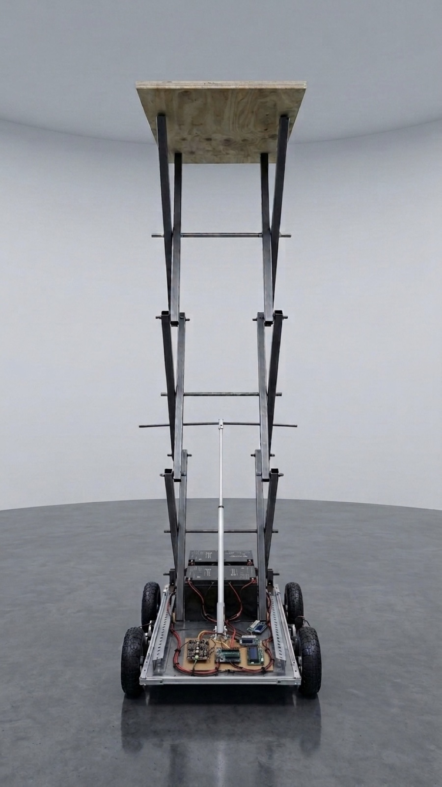
Finished platform, fully extended